Do jet engines have spark plugs?

December 20, 2025
Jet engines are internal combustion engines that generate thrust by the combustion of fuel and air. To begin the combustion process, high-pressure, high-temperature air is mixed with pressurized fuel and ignited using ignitors (may also be called spark plugs).
The term “spark plug” is generally used in piston engines, where a single spark is timed in each cylinder for every power stroke. The spark plug provides continuous power while the engine is running.
A jet engine ignitor, on the other hand, is designed to provide a continuous stream of sparks during the starting sequence or under extreme conditions. Once the fire is lit, the ignitor is switched off while the flame becomes self-sustaining.
The jet engine ignition system
The ignition system on a jet engine typically consists of two ignition exciters, two ignition leads, and two ignitors. The ignition system is designed to provide the necessary electric power, primarily during the engine startup phase. Having a pair of ignitors allows higher power output while enabling more efficient fuel burn. The aircraft electrical system provides AC power to the engine exciters.
Ignition exciters convert the voltage to DC and transmit high-energy pulses to the ignitors through the ignition leads. The continuous-type ignition system provides power during critical phases of flight, including takeoff, landing, and inclement weather conditions.
Ignition exciters consist of capacitor charging and discharging circuits enclosed in an aluminum case. Depending on the type and thrust rating of the engine, exciters provide anywhere between 10,000 and 20,000 volts DC output, at approximately one pulse per second. Notably, circuit elements within the exciters isolate the unit from interference from aircraft electronics.
The ignition leads deliver low-energy, high-voltage electric pulses from the exciters to the ignitors. A surface gap at the tip discharges the high voltage pulse. The leads provide cooling airflow to the ignitor plug and connection, keeping the temperatures in check. The cold air from the engine bypass is routed from aft of the fan case to the ignition leads.
Ignitors consist of center electrodes, providing the necessary electrical sparks to start and maintain combustion. The plugs are protected from compartment heat by means of shrouds. Typically, only one ignitor is used when on the ground. The electronic control unit (ECU) alternates ignitors between every 1-2 flights in manual and auto modes. Both ignitors remain active when the aircraft is in the air.
Continuous ignition in a jet engine
The jet engine ignitor lights the fire to begin combustion before turning off, allowing the system to become self-sustaining. However, when jet engines experience airflow disruptions, continuous ignition becomes necessary to prevent flameout. Apart from the initial startup process, the ignition system enforces continuous ignition during a range of flight conditions.

Heavy precipitation and icing conditions enable the use of continuous ignition of jet engines. During severe precipitation, large quantities of water may interfere with the combustion process, requiring backup from the ignitors. Similarly, ignitors are turned on before entering icy conditions during flight.
It is done to prevent the engine from flaming out should the oncoming ice interfere with the airflow through to the combustor. It is noteworthy that the same conditions may apply when taking off from or landing on wet or contaminated runways.

Turbulence during flight can also disrupt the constant airflow. Ignitors may be switched on to prevent a flameout event as a result of severe turbulence. In low fuel pressure or a low quantity event, ignitors may be kept on to allow continuous engine operation.
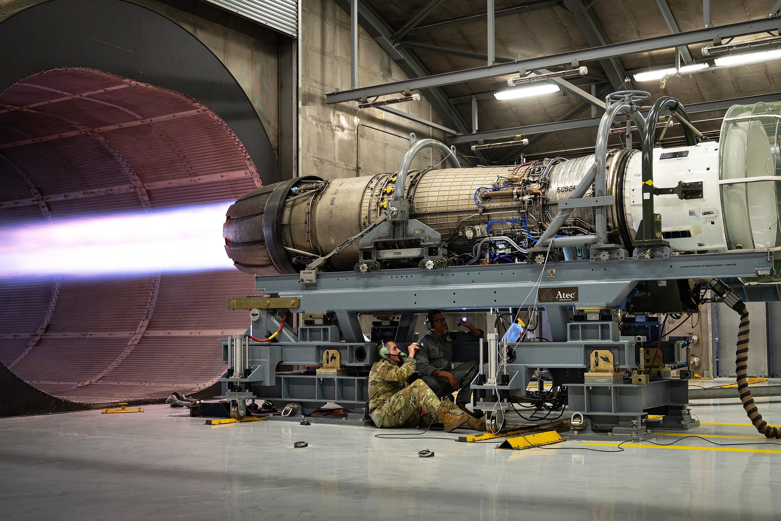
Featured image: USAF